SLIM-MXR-4
Mixer with Diplexer
Updated
6-13-08. Updated to reflect Revision A
Updated
8-11-09. Add information and revision history
Updated
1-20-16. Update and move Parts List to this page
SLIM-MXR-4,
Mixer, size-A
Use your mouse's "right click" and "Save Link" to download:
a. SKSLIM-MXR-4.sch
Rev A ,
Schematic, in ExpressPCB software.
b. LAYSLIM-MXR-4.pcb
Rev A,
Layout, in ExpressPCB software.
Use this drawing to locate
the parts on the SLIM Board.
c. PLSLIM-MXR-4
Parts
List. Maintained only on this page.
d. PWB-MXR-ADE.pcb
Rev 0, Base artwork for PWB, in ExpressPCB
software.
Use this drawing to order the pwb from Express. This is the base
configuration for design of the SLIM-MXR-4.
Click to get full information for a basic mixer design on the PWB-MXR-ADE
page.
The SLIM-MXR-4 was
designed to be used for the Mixer 4 addition
when expanding the MSA/TG into a Vector Network Analyzer, VNA .
It was a replica of SLIM-MXR-2, using the same schematic and
parts list. Since then, SLIM-MXR-4 has been revised
and has its own documentation.
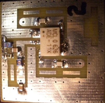
J1 is
the Local Oscillator input port. J3 is used as the RF Input
port. J2
is used as the down converted IF output port. Pin 2 of the
ADE-11X is
connected to its internal diode bridge, which is responsive down to 0
Hz. This module can be used in other applications, but
it is probably better to use the basic PWB-MXR-ADE
and custom design the components for your specific application.
Minicircuits specifies the conversion
loss at -7.5
dB. I measured the conversion loss at -6.5 dB.
The strange looking circuit in the
I port path is a diplexer. Wide band frequencies (and noise)
exiting
the mixer at the I port "see" a dual path at the junction of L15,
C16. Frequencies higher than 33 MHz follow C16 and get absorbed
by
the 50 ohm load at R17. Frequencies lower than 33 MHz follow L15
and are launched at J2. This gives the mixer a constant 50 ohm
load over a very wide frequency range, making it very "happy".
The diplexer could be re-designed for any frequency crossover point.
The Revision B added a 2.5 dB attenuator
in the J1,
LO input port. This addition makes the Mixer's L port a better 50
ohm match, but it makes it necessary for
the LO Drive into the module to be
approximately +9.5
dBm. For lower drive levels, ie, +7 dBm, the attenuator should be
removed. However, I have tested this module with as
little as +4.5 dBm at J1 (+2 dBm on
the ADE-11X's L port) with only an additional -1 dB of conversion loss.
The upgrade from SLIM-MXR-4
Rev 0 to Rev A is quite simple.
Revision History
Original Release: Released
7-08-2007
SLIM-MXR-4 Rev 0, used SK-MXR-2 Rev 0, PWB-MXR-ADE Rev 0, used
PLSLIM-MXR-2 Rev 0
Revision A: Revised
6-11-08
SLIM-MXR-4 Rev A, SKSLIM-MXR-4 Rev A, PWB-MXR-ADE Rev 0,
PLSLIM-MXR-1 Rev A
1. Added a 2.5 dB attenuator network in the L
port
path to the
mixer. This provides a better impedance match between the LO
input
connector - J1, and the mixer.
2. Added a 14 dB attenuator network in the
R port path to the
mixer. This provides a better impedance match between the R input
connector - J3, and the mixer.
These modifications improve the mixer isolation.
Revised 9-08-2008: errors on Parts
List, revised to PLSLIM-MXR-4 Rev B. No other changes.
SLIM-MXR-4 Rev A, SKSLIM-MXR-4 Rev A, PWB-MXR-ADE Rev 0,
PLSLIM-MXR-1 Rev B