Updated
6-13-08. Updated to reflect Revision A Updated
1-08-09. Optional modification to minimize high
frequency mismatch when using the SLIM-MXR-1 in the Modular Spectrum
Analyzer (MSA) Updated
8-11-09. Add information and revision history.
Describe optional
attenuator on J2 port. Updated
1-20-16. Move Parts List to this page.
SLIM-MXR-1,
Mixer, size-A
Use your mouse's "right click" and "Save Link" to download:
a. SKSLIM-MXR-1.sch
Rev A,
Schematic, in ExpressPCB software.
b. LAYSLIM-MXR-1.pcb
Rev A,
Layout, in ExpressPCB software.
Use this drawing to locate
the parts on the SLIM Board. Do not use for ordering the pwb from
Express.
c. PLSLIM-MXR-1
Parts List. Maintained only on this page.
d. PWB-MXR-ADE.pcb
Rev 0 ,
Base artwork for PWB, in ExpressPCB software.
Use this drawing to order the pwb from Express. This is the base
configuration for design of the SLIM-MXR-1.
Click to get full information for a basic mixer design
on the PWB-MXR-ADE
page.
The SLIM-MXR-1 is configured with the
Minicircuits,
ADE-11X. This mixer has only a fair L port to R port
isolation (mixer pin 3 to pin 6). Minicircuits
specifies it as -38 dBc, but I
measure it
closer to -30 dBc at 1000 MHz. They specify the conversion loss
at -7.5
dB. I measured the conversion loss at -6.5 dB. I continue
to recommend this mixer, but only because of it's very low cost.
Updated
7-23-09
SLIM-MXR-1 has been designed specifically
to be used in the MSA for its Mixer 1 position. J1 is
the Local Oscillator input port. J2 is used as the RF Input
port. J3
is used as the up converted IF output port. Module J2 is Pin
2 of the ADE-11X, which
is
connected to its internal diode bridge. It is responsive down to 0
Hz. This module can be used in other applications, but
it is probably better to use the basic PWB-MXR-ADE
and custom design the components for your specific application.
When SLIM-MXR-1 is used with
the MSA, I recommend that it be constructed to Rev A, with the addition
of the optional input attenuator modification (see next
paragraph). I also recommend the optional
R port Modification (see bottom of page). The SLIM-MXR-1
Rev 0 is very easily to upgrade to Rev A.
Updated
7-23-09: Optional
Input Attenuator Modification
This is not shown in the schematic but an attenuator
can be added in the J2 path to make the SLIM-MXR-1
a better 50 ohm load to external signal sources. R15 is replaced
by a
pi-type attenuator with resistor values to conform to the wanted
attenuation. Components not shown are the input shunt resistor,
R11
and output shunt resistor, R19. Locate these
components on the Layout, later on this page. For
example: a 6 dB attenuator would consist of R11=150 ohms, R15=37.4
ohms, and R19=150 ohms.
Revision History Original Release: Released
7-01-2007
SLIM-MXR-1 Rev 0, SK-MXR-1 Rev 0, PWB-MXR-ADE Rev 0, PLSLIM-MXR-1 Rev 0
Revision A: Revised 6-11-08
SLIM-MXR-1 Rev A, SKSLIM-MXR-1 Rev A, PWB-MXR-ADE Rev 0,
PLSLIM-MXR-1 Rev A
Added a 2.5 dB attenuator network in the L port
path (J1)
to the
mixer. This provides a better load match from the driving module
(PLO 1). This also improves the internal mixer
isolation. With this mod, the L to R port isolation will approach
the
specification of Minicircuits.
This attenuator makes it necessary for
the LO Drive at J1 to be
approximately +9.5
dBm. For lower drive levels, ie, +7 dBm, the attenuator should be
removed. However, I have tested this module with as
little as +4.5 dBm at J1 (+2 dBm on
the ADE-11X's L port) with only an additional -1 dB of conversion loss.
Revised 9-08-2008: errors on Parts
List, revised to PLSLIM-MXR-1 Rev B. No other changes.
SLIM-MXR-1 Rev A, SKSLIM-MXR-1 Rev A, PWB-MXR-ADE Rev 0,
PLSLIM-MXR-1 Rev B
SKSLIM-MXR-1,
Schematic of SLIM-MXR-1
The coupling resistor R15 is a
short circuit (zero ohm resistor), allowing all frequencies to
pass. C25 is a low value capacitor to allow only high frequencies
to pass.
Parts List, PLSLIM-MXR-1 Revision B, 9-8-2008
(updated 1-23-2016) Desig. Value
Part Number
Digikey
Number
Cost
Notes
C5
"Rev A, deleted 100 pf"
C25 100 pF C0805C101K5GACTU
399-1121-1-ND
0.05
J1 SMA optional Molex, 538-73391-0070
WM5544-ND
4.74
J2 SMA optional Molex,
538-73391-0070
WM5544-ND
4.74
J3 SMA optional Molex,
538-73391-0070
WM5544-ND
4.74
R1 330
MCR10ERTF3300
RHM330CHCT-ND
0.04 was MCR10EZHF330/RHM330CCT-ND
R5 15
MCR10ERTF15R0
RHM15CHCT-ND
0.04 was MCR10EZHF15.0/RHM15.0CCT-ND
R9 330
MCR10ERTF3300
RHM330CHCT-ND
0.04 was MCR10EZHF330/RHM330CCT-ND
R15 0 MCR10EZHJ0.0
RHM0.0ACT-ND
0.08
MXR ADE-11X
Minicircuits
2.95
PWB Circuit Board
PWB-MXR-ADE
3.28
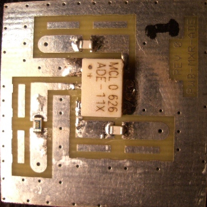
LAYSLIM-MXR-1, Parts
locator for SLIM-MXR-1
This layout shows the L port attenuation but no other
modifications.. The picture shows the original
circuit.
Updated
1-08-09. Optional R port Modification
When this module is used in the
MSA, the user may find
that the Spectrum Analyzer's Magnitude Gain
versus Frequency may have an abrupt change at some frequency below 400
MHz. This is due to the Coaxial Cavity Filter path creating a
mismatch
for Mixer 1 at frequencies other than the prescribed First Intermediate
Frequency of 1013.3 MHz. This mismatch can be minimized with a
simple
modification to the SLIM-MXR-1 module. The schematic, layout, and
parts list will not be revised for this modification, since it is
optional. Use the general PWB layout below, to perform the
Modification
procedure:
1. Add a 1 pfd capacitor in the X26 position. This is the
ADE-11X, R port, pin 3.
2. Add a 49.9 ohm resistor in the X27
position. The value is not critical, from 43 to 62 ohms is fine.
These two series components act as a load for high frequency
reflections from the Cavity Filter.