SLIM-IFA-33 rev A
IF Amplifier Module
Updated
4-30-08. Update page to reflect Revision A.
Updated
5-16-15. Move Parts List to this page, change
capacitors, Change Parts List to Rev B.
Updated
1-13-16. Update L27, L37 on Parts List, Rev C.
SLIM-IFA-33,
I.F. Amplifier, size-A
Use your mouse's "right click" and "Save Link" to download:
a.
SKSLIM-IFA-33 rev A,
Schematic, in ExpressPCB software.
b. LAYSLIM-IFA-33 rev A,
Layout, in
ExpressPCB software. Use for locating parts on board.
c. PWB-RFA,
PWB artwork, in
ExpressPCB software. Use for ordering from Express.
d. PLSLIM-IFA-33 Rev C. Parts List, maintained
on
this page only.
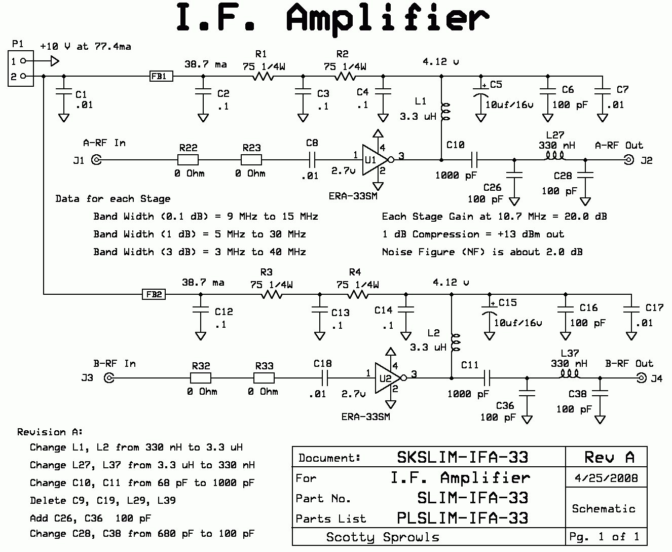
The SLIM-IFA-33 Amplifier module consists of two
separate MMIC amplifiers with a common DC power input connector.
The
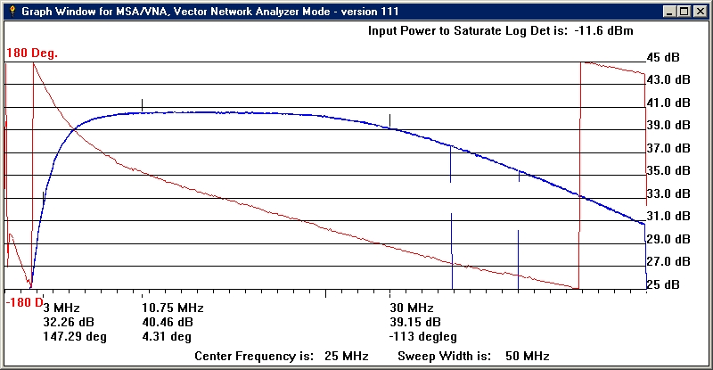
MMICs have a bandwidth of over 4 GHz, so a 40 MHz low pass filter is
included
in each output. At 10.7 MHz, the single stage gain is 20 dB, with
a 1
dB compression point output of greater than +13 dBm.
Noise figure is less than 3 dB. 38 ma. of
bias current (for each amplifier) is required to maintain these
specs. With +10 volts
input to the module, a total of 150 ohms dropping resistance is
required. The dropping resistance is split
into two 75 ohm resistors, each dissipating 108 milliwatts. The
split resistors also allow for more input power filtering.
This module was given the suffix "-33" because it specifies
using the MiniCircuits ERA-33 MMIC. However, other MMIC's can be
substituted (with appropriate bias component changes). The bandwidth
limitation of the circuit can be increased by removing or changing the
output low pass filter. The design of 40 MHz was due to the use of this
module as a 10.7 MHz amplifier in the MSA.
SKSLIM-IFA-33, Schematic of SLIM-IFA-33


