SLIM-PLO-1 rev C
Phase Locked
Oscillator
with Active Loop
Updated
7-23-09. Update page to reflect Revision C and
modification to Rev B.
Updated
8-11-09. Update information. Add release
history.
Updated
12-26-10. Update PLL chip support and move
Parts List to this page.
Updated
5-13-15. Change Parts List to Rev F. C6, C8,
C10, C16, C33, C40, and C46 are changed. Remove Release History.
Updated
5-3-17. Update parts list to include alternate
VCO
SLIM-PLO-1,
Phase Locked Oscillator with
active loop,
size-B
Use your mouse's "right click" and "Save Link" to download:
a. SKSLIM-PLO-1.sch rev C,
Schematic, in ExpressPCB software.
b. LAYSLIM-PLO-1.pcb rev B,
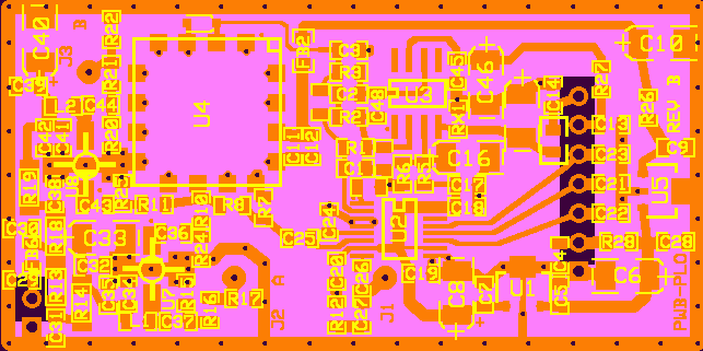
Component Layout, in ExpressPCB software. Use to locate parts on
board.
c. PLSLIM-PLO-1.rev F, Updated 1-23-16.
Maintained only on this page.
d. PWB-PLO.pcb rev B,
Master Artwork, in ExpressPCB software. Use to order pwb
from Express.
e. PLO1revC.pll
PLL Simulation. Open with ADIsimPLL Version 3.0
This SLIM is constructed on a common printed
wiring
board, the PWB-PLO. Click to get full
information on the Basic Phase
Locked Oscillator.
SLIM-PLO-1
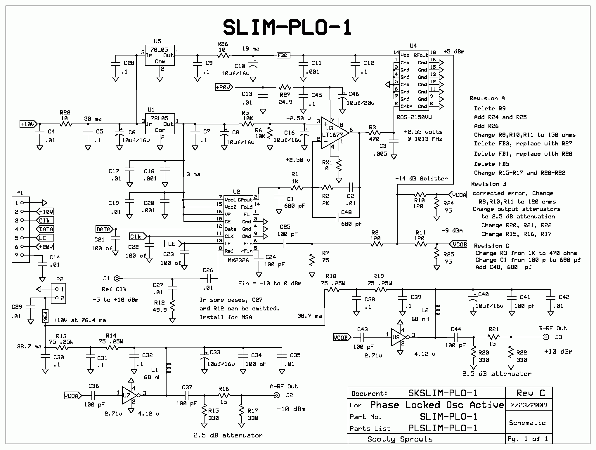
Frequency output = 950 MHz to 2200 MHz. PLL is
LMX
2326 or ADF 4118. The loop filter is active, using an Op
Amp. A
negative supply voltage is not required. Dual RF outputs, +8 to
+10
dBm at J2 and J3. Phase noise at 1000 MHz is -91 dBc (1
Hz BW), 5
KHz away from carrier.
R12 and C27 are
optional. Installed, they present a 50 ohm load to the
driver. Omitted, the PLL is high impedance CMOS logic. For
best spur rejection, they should be installed.
Notice: It is possible that the power outputs at J2 and J3
may be low. The most likely cause is that the output power of the
Minicircuits VCO, ROS-2150VW, is lower than specification. Its output
power can be increased by increasing the voltage supply at the VCO (U4
pin 14) to +6.0 volts, +/- .1volt. This will increase the output
power of the VCO by 2 to 3 dB. There are two ways to do this:
1. Change the LM74L05 to a 6v or 6.2v regulator.
Replace R26 with a value of resistance to assure 6.0 volts at the VCO,
U4 pin 14. The nominal current of the VCO is about 20 ma.
Or,
2. Remove the voltage regulator, U5. Reinstall U5,
but do not connect it's power tab or it's pin 2 to ground. Add
two diodes in series, between U5-2 to ground. Anode to U5-2 and
cathode to ground. Add a 1.0 ufd capacitor from U5-2 to
ground. The output of U5 will increase to about 6.2 to 6.4 volts.
Replace R26 with a value of resistance to assure 6.0 volts at
the VCO, U4 pin 14. The nominal current of the VCO is about 20 ma.
Another option is to replace the U7 and U8 amplifiers from the ERA-33SM
to the Minicircuits LEE-39 or LEE-59.They have about 2 dB more gain.
The supply bias resistors would need to be modified for proper current.
I have not tried this change. It was suggested by an MSA user.
SKSLIM-PLO-1, Schematic of SLIM-PLO-1, Revision C


