For
a filter, normal Transmission mode graph will display the
profile of the filter response. As in Spectrum Analyzer mode, the P+
and P-
markers may be used to automatically locate peaks and valleys. In
addition,
there is a Filter Analysis feature available under the Analysis menu
that opens
the following window.
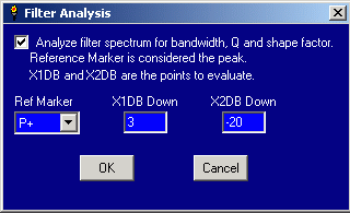
Filter
Analysis. The Filter Analysis Function. a PDF file by Sam Wetterlin.
In
this window, the user can turn filter analysis on or off, indicate what
marker
is to mark the peak, and also indicate the dB points to mark. Here we
have
marked that we want the points that are 3 dB down, and “-20” dB down.
The
dialog allows the dB values to be positive or negative, but always
interprets
them as being below the reference marker.
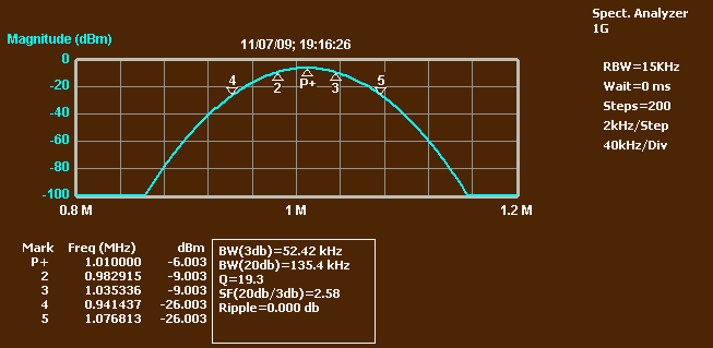
When
OK is clicked, the MSA will place markers at the appropriate points on
the
graph.
In
this case, markers 2 and 3 are placed at the -3dB points, and
markers 4 and 5 are placed at the -20 dB points. If the scan continues,
the
position of the markers will be adjusted at the end of each scan. The
marker
data is displayed below the graph, and some additional data is
displayed
describing the filter characteristics: the bandwidth at -3 dB and -20
dB, Q,
the shape factor (the ratio of the -20 dB and -3 dB bandwidths), and
the
ripple. The ripple is measured between the -3 dB points, and with such
a nice
rounded peak it is zero.