PWB-MCF rev A
Monolithic Crystal Filter
Monolithic Crystal Filter
Updated 4-30-08. Update page to describe construction of different filters, all using the same pwb, part number: PWB-MCF.
Updated 6-17-09. Update page to describe "How To" match a Crystal Filter to 50 ohms.
Updated 8-11-09. Add more information, and a revision history.
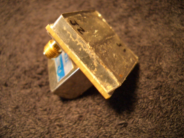
PWB-MCF, pwb for Monolithic Crystal Filter, size-A
The PWB-MCF is a generic printed wiring board that is designed and layed out to accommodate a variety of multipole, Monolithic Crystal Filters. The board is split into two sections with a center fence as a separator.
This page will describe the PWB-MCF and various SLIM crystal filters that can be constructed on it. The SLIM-MCF-xxxx part numbers are "place holders" until a good, reputable monolithic crystal can be identified and a supplier found.
Some filter part numbers shown on this page: L024, FL096, QMF 10725, QMF 10713. If you have a favorite Monolithic Crystal Filter in the range of 9 MHz to 15 MHz, please let me know about it. I will include it on this page. (wsprowlsatyahoodotcom)
Revision History
Original Release: PWB-MCF Rev 0, 7-01-2007
Revision A: PWB-MCF Rev A, 4-30-2008
Initial testing of Rev 0 showed poor isolation performance. The input connector and output connector were too close together to get really, good isolation performance. I could only get -84 dBc input to output isolation. The "pass-thru" seemed to be through the FR4 material, right through the line of central ground vias. I would consider this a fault of the pwb material, not my basic layout design. I had used the scheme with even closer connectors and have never had this amount of poor isolation. Therefore, I modified the pwb layout to extend the distance between connectors.
Artwork for PWB-MCF, and parts locator for SKPWB-MCF
PWB-MCF.pcb rev A, Base artwork for PWB, in ExpressPCB software. Download this drawing to order the pwb from Express, or to locate the parts for a generic filter.
There are no board vias designed to accomodate a specific filter. The idea is to drill holes for the filter leads and solder the filter on the bottom side of the pwb. The filter is mounted on the bottom side of the pwb with the leads extending through to the top layer. The perimeter of the Crystal filter is soldered to the bottom ground plane. The top layer has a full perimeter shield fence and another shield fence separating the two sections. Two "lids" are soldered to the top of the fences. Various matching circuits, filtering, or attenuators can be added, using the available pads on the component side of the board.
Generic Schematic for PWB
SKPWB-MCF.sch Rev A, Generic Schematic for PWB-MCF, in ExpressPCB software. The difference between Rev 0 and Rev A: I changed all the reference designators and removed specific values. Attenuators X1-X3 and X8-X10 could be pi-type low pass filters with impedance transformation. Up to the user.
No matter what monolithic filter you use, the characteristic impedance will not be exactly as the manufacturer claims. Also, the input and output impedances may not be the same. The specs are usually close enough to give good results using standard inductors and capacitors. If the builder would like to critically tune the filter, the impedance matching inductors and capacitors need to be variable or selectable. The fixed input capacitors, X5 and X6, could be decreased in value by 15 pfd and a small (2-20 pfd) variable placed in shunt with the fixed capacitors. The inductors, X4 and X7, could be wound as toroids and be adjustable by removing or adding turns. This critical tuning can improve the bandpass ripple by as much as 1 dB and decrease insertion loss by, perhaps, .5 dB.
How to match a Crystal Filter to 50 ohms. Added, 6-17-09
Use the generic schematic above. Not shown is the effective shunt capacitance internal to the crystal filter. It can vary from a few pfd to hundreds of pfd. It is referred to as Cin. Also not shown is the effective input shunt resistance, Rin. These two values are usually given by the manufacturer of the Crystal Filter and specified as the input impedance, Zin. or just Z. For example Zin = 2K//4pfd. Zin is equal to a shunt AC resistance (Rin) of 2,000 ohms in parallel with the shunt capacitance (Cin) of 4 pfd. For this modeling, I will use the the values, Rin = 2K ohms and Cin = 4 pfd. I will use a Center Frequency of 11.4 MHz.
The first thing to do is pretend that Cin = 0 pfd, that is, the Crystal Filter has an impedance that is a pure resistance (Rin) of 2K ohms, shunted to ground. We will create an "L" type LC circuit to transform 50 ohms to 2,000 ohms at 11.4 MHz. This LC circuit could be either a "high pass" or "low pass" configuration. Crystal Filters are usually quite poor at attenuating very high frequencies. Therefore, when impedance matching Crystal Filters, ALWAYS use a "low pass" configuration. This means the matching circuit will have a series inductor (Lm), and a shunt capacitor (Cm). In the above schematic they are labeled, X4 and X5 (or X6, X7).
Next, assuming a purely resistive input impedance, we can calculate the nominal coupling components, Cm and Lm.
Cm = 1/ [2*pi*f*sqrt(Rin*50)] = 1/ [6.28*11.4M*sqrt(2K*50)] = 44 pfd
Lm = sqrt(Rin*50)/(2*pi*f) = sqrt(2K*50)/(6.28*11.4M) = 4.4 uH
Both X4 and X7, in the above schematic, will be Lm, which is 4.4 uH. The closest manufactured inductor is 4.3 uH, but this is close enough. You can wind your own inductor on a small toroid to be more precise. I will not get into those details here.
The calculation says that both X5 and X6 (Cm) should be 44 pfd. However, since the internal capacitance (Cin) of the Crystal Filter is 4 pfd, you subtract the internal 4 pfd from the total of 44 pfd and get 40 pfd for X5 and X6. The closest manufactured capacitor is 39 pfd or 41 pfd, but either is close enough. You could use a fixed capacitor of 36 pfd, and add a shunt variable capacitor of 1-10 pfd.
It is important to say that when adding components outside of the Crystal Filter, they will act like little antennas, and couple input signals to the output. To prevent this, isolate the input side of the Crystal Filter from the output side. Do this by adding a shield in the center of the Crystal Filter. Look at the artwork for the PWB, above. You will notice a series of ground vias in the center of the board (labeled Fence). This is where to place your shield.
You will notice that there are no layout vias to mount a Crystal Filter. This is because this PWB will accomodate many sizes of Filters. You must drill your own holes to match your chosen filter. The Crystal Filter is mounted on the bottom of the PWB with its terminals protruding through the newly drilled holes. (Be sure to trim the ground layer away from the "hot" terminals). For best results, "perimeter solder" the Crystal Filter on the bottom side of the PWB. However, use caution. Excess heat can de-solder internal components of the filter.
SLIM-MCF-L024, 10.695 MHz, Monolithic Crystal Filter, size-A
This module, using the 10L024, is a "blind" design, and is a place holder until I can find a good, inexpensive MCF that the home builder can easily acquire.
Schematic for SLIM-MCF-L024
SKSLIM-MCF-L024.sch Rev 0, Schematic for SLIM-MCF-L024, in ExpressPCB software.
PLSLIM-MCF-L024.txt Rev 0, Parts List in text format.
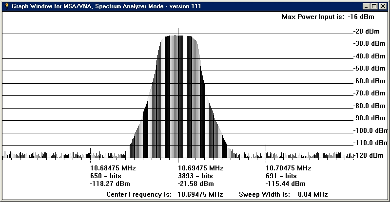
The filter shown (XF) is distributed by U.S. Electronics. However, their minimum quantity is 1000. It has a center frequency of 10.695 MHz. The bandwidth is 2.2 KHz and has a loss of -4.5 dB. It has a 600 ohm inut/output impedance.
This module, using the 10L024, is a "blind" design, and is a place holder until I can find a good, inexpensive MCF that the home builder can easily acquire.