the Modularized Spectrum Analyzer
Interested in owning your own RF Spectrum Analyzer ?
This site is dedicated as a Home Experimenter's Guide to building a Quality,
yet, Inexpensive 1000 MHz Spectrum Analyzer.
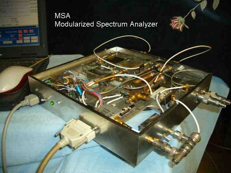
The
Original MSA, mated with a laptop computer. Not pretty, but works
quite well.
The newer version, the SLIM MSA.


Same concept, but constructed using Standardized Laboratory Integration Modules, SLIM's.
Updated Aug. 11, 2017 Updated software to Version 118. Download software from Initial Set-Up and Calibration of the MSA
The MSA project was started in Jan, 2001 and has evolved under several titles.
By Scotty Sprowls
If you want to build your own Home-Brew 1000 MHz Spectrum Analyzer, you already have half of it completed. That half is the computer you are using to read this. The processors and displays are very expensive portions of modern spectrum analyzers, and those functions can be replaced by your home computer. The computer's monitor is the Spectrum Analyzer's display. The other half is the MSA hardware, to be constructed (as seen in the photos). The MSA Software is free to download. It will operate on any computer with a parallel port, USB 2, or USB3 and any Microsoft Windows platform. USB operation has been tested using Win ME, Win XP, Win7, Win8, and Win10.
Previous visitors to this Site will notice significant changes. I have deleted most references to previous versions of the MSA and will concentrate on the MSA using SLIMs, Standardized Laboratory Integration Modules. The previous designs and web pages are retained in the MSA Archives, for those who need the references. The SLIM MSA does not obsolete the Original MSA design. The Original MSA will continue to be supported in the software.
The title of this page and the opening paragraph seem to indicate that the Function of the MSA is a Spectrum Analyzer with operation limited to 1000 MHz. This was my original concept and design goal. However, software and hardware additions have allowed the MSA to provide many more Functions than just that of a Spectrum Analyzer. The Functions depend upon the level of construction. There are 3 Build Levels of the MSA.
Basic MSA, Build Level 1:
The Basic Modularized Spectrum Analyzer (Level 1) is the core of the MSA Project It is comprised of 11 modules and is common to all higher levels of construction. Its basic function is that of a
Spectrum Analyzer, with these specifications:
3 band ranges: 0-1 GHz, 1-2 GHz, and 2-3 GHz (or higher using harmonic mixing)
Frequency Resolution: less than 3 Hz
Instantainous Dynamic range: greater than 100 dB. Average 110 dB.
Sensitivity: -20 dBm to -120 dBm
Resolution Bandwidth: Optional, with Resolution Bandwidth filter selection.
When not used as an SA, the Basic MSA can provide these other Functions:
Logging Voltmeter (future development with A to D Converter)
Frequency Sources:
Fixed, 64 MHz Clock Source, 50 ohm, square (Master Oscillator)
Variable, 1-1.5 GHz, 50 ohm, sine. Selectable in steps. (PLO 2)
Variable, 1-2 GHz, 50 ohm, sine, <3 Hz resolution. (PLO 1)
Variable, 0-1 GHz, 50 ohm, sine, <3 Hz resolution. (PLO 1 - PLO 2)
Variable, 2-3 GHz, 50 ohm, sine, <3 Hz resolution. (PLO 1 + PLO 2)
CW or Swept DDS Signal Generator, 0-32 MHz, 50 ohm, sine, 0.014 Hz resolution. (DDS 1)
MSA with Tracking Generator, MSA/TG, Build Level 2:
Build Level 2 is the addition of 3 modules to add a Tracking Generator to the Basic MSA. The following functions are added:
Spectrum Analyzer with Signal Generator
Spectrum Analyzer with Tracking Generator
Normal Tracking Generator, or
Offset Tracking Generator, or
Reversed Tracking Generator, with or without offset
Scalar Network Analyzer
Crystal Analyzer, a Crystal Tester
Additional Frequency Sources:
Variable, 1-2 GHz, 50 ohm, sine, <3 Hz resolution. (PLO 3)
CW or Swept DDS Signal Generator, 0-32 MHz, 50 ohm, sine, 0.014 Hz resolution. (DDS 3)
VNA, Vector Network Analyzer, MSA/TG/VNA, Build Level 3:
This is the addition of 2 more modules to the MSA/TG (Build Level 2) to create a Phase Measurement System.
Vector Network Analyzer, Transmission
Vector Network Analyzer, Reflection
The VNA has the same Functions as the Basic MSA and MSA/TG, plus the Functions:
Filter Analyzer
RLC Analysis, Circuit conversion
Component Meter, for measuring resistors, capacitors, inductors.
Coax Tester, a Transmission Line Analyzer
Antenna Analyzer
MSA Requirements for the Home Computer and its Software:
PC or Laptop Computer (any speed), with USB 2 or LPT standard or enhanced parallel port (SPP, EPP). Monitor can be any size, but MSA software uses 800 by 600 pixel resolution. Windows 98 or later. MSA software is executable, but builders who wish to modify the MSA software will need Liberty Basic 4.03. The Liberty Basic is free, but it will nag you to buy it. Go visit their web site at www.libertybasic.com.
MSA Web Pages supporting the MSA Project. Some are still in-work:
Construction of the SLIM MSA, a Construction Guide for integrating the MSA using Standardized Lab Integration Modules. The Basic MSA, Tracking Generator addition, and Vector Network Analyzer extension are covered. Specifications for the SLIM MSA and links to pages for the construction of the individual SLIMs.
Construction Hints. Hints on constructing the SLIMs. It may save you a lot of potential grief.
Initial Set-Up and Calibration of the MSA, including instructions for downloading the software.
Test-As-You-Build, A test procedure for SLIMs as they are built and integrated into the MSA.
Testing the Integrated MSA, A test procedure and troubleshooting guide for a fully integrated MSA.
Control and Operation of the MSA is common to all Build Levels of the MSA. A description of screens, controls, and operation.
Technical Analysis of the MSA. In-depth circuit analysis. Very handy for troubleshooting the MSA.
Temperature Testing of the MSA. Testing the MSA/VNA for temperature induced error. In-work.
SLIM Web Page. The Standardized Laboratory Integration Module philosophy and links supporting the SLIMs.
Coaxial Cavity Filter, description and construction of a high-Q, 1013 MHz bandpass filter.
USB control for the MSA.
Using the MSA to Test Phase Noise of PLO 2, DDS 1 as a Low Phase Noise Sweep Source
Using the DDS 1 to Sweep a Crystal Filter, DDS 1 as a Tracking Generator or Scalar Network Analyzer
MSA Archives, old stuff no longer maintained. Use it, but many links don't work. I will repair them as time permits.
VNA Operating Guide, by Sam Wetterlin
The newer version, the SLIM MSA.
Same concept, but constructed using Standardized Laboratory Integration Modules, SLIM's.
Updated Aug. 11, 2017 Updated software to Version 118. Download software from Initial Set-Up and Calibration of the MSA
The MSA project was started in Jan, 2001 and has evolved under several titles.
By Scotty Sprowls
If you want to build your own Home-Brew 1000 MHz Spectrum Analyzer, you already have half of it completed. That half is the computer you are using to read this. The processors and displays are very expensive portions of modern spectrum analyzers, and those functions can be replaced by your home computer. The computer's monitor is the Spectrum Analyzer's display. The other half is the MSA hardware, to be constructed (as seen in the photos). The MSA Software is free to download. It will operate on any computer with a parallel port, USB 2, or USB3 and any Microsoft Windows platform. USB operation has been tested using Win ME, Win XP, Win7, Win8, and Win10.
Previous visitors to this Site will notice significant changes. I have deleted most references to previous versions of the MSA and will concentrate on the MSA using SLIMs, Standardized Laboratory Integration Modules. The previous designs and web pages are retained in the MSA Archives, for those who need the references. The SLIM MSA does not obsolete the Original MSA design. The Original MSA will continue to be supported in the software.
The title of this page and the opening paragraph seem to indicate that the Function of the MSA is a Spectrum Analyzer with operation limited to 1000 MHz. This was my original concept and design goal. However, software and hardware additions have allowed the MSA to provide many more Functions than just that of a Spectrum Analyzer. The Functions depend upon the level of construction. There are 3 Build Levels of the MSA.
Basic MSA, Build Level 1:
The Basic Modularized Spectrum Analyzer (Level 1) is the core of the MSA Project It is comprised of 11 modules and is common to all higher levels of construction. Its basic function is that of a
Spectrum Analyzer, with these specifications:
3 band ranges: 0-1 GHz, 1-2 GHz, and 2-3 GHz (or higher using harmonic mixing)
Frequency Resolution: less than 3 Hz
Instantainous Dynamic range: greater than 100 dB. Average 110 dB.
Sensitivity: -20 dBm to -120 dBm
Resolution Bandwidth: Optional, with Resolution Bandwidth filter selection.
When not used as an SA, the Basic MSA can provide these other Functions:
Logging Voltmeter (future development with A to D Converter)
Frequency Sources:
Fixed, 64 MHz Clock Source, 50 ohm, square (Master Oscillator)
Variable, 1-1.5 GHz, 50 ohm, sine. Selectable in steps. (PLO 2)
Variable, 1-2 GHz, 50 ohm, sine, <3 Hz resolution. (PLO 1)
Variable, 0-1 GHz, 50 ohm, sine, <3 Hz resolution. (PLO 1 - PLO 2)
Variable, 2-3 GHz, 50 ohm, sine, <3 Hz resolution. (PLO 1 + PLO 2)
CW or Swept DDS Signal Generator, 0-32 MHz, 50 ohm, sine, 0.014 Hz resolution. (DDS 1)
MSA with Tracking Generator, MSA/TG, Build Level 2:
Build Level 2 is the addition of 3 modules to add a Tracking Generator to the Basic MSA. The following functions are added:
Spectrum Analyzer with Signal Generator
Spectrum Analyzer with Tracking Generator
Normal Tracking Generator, or
Offset Tracking Generator, or
Reversed Tracking Generator, with or without offset
Scalar Network Analyzer
Crystal Analyzer, a Crystal Tester
Additional Frequency Sources:
Variable, 1-2 GHz, 50 ohm, sine, <3 Hz resolution. (PLO 3)
CW or Swept DDS Signal Generator, 0-32 MHz, 50 ohm, sine, 0.014 Hz resolution. (DDS 3)
VNA, Vector Network Analyzer, MSA/TG/VNA, Build Level 3:
This is the addition of 2 more modules to the MSA/TG (Build Level 2) to create a Phase Measurement System.
Vector Network Analyzer, Transmission
Vector Network Analyzer, Reflection
The VNA has the same Functions as the Basic MSA and MSA/TG, plus the Functions:
Filter Analyzer
RLC Analysis, Circuit conversion
Component Meter, for measuring resistors, capacitors, inductors.
Coax Tester, a Transmission Line Analyzer
Antenna Analyzer
MSA Requirements for the Home Computer and its Software:
PC or Laptop Computer (any speed), with USB 2 or LPT standard or enhanced parallel port (SPP, EPP). Monitor can be any size, but MSA software uses 800 by 600 pixel resolution. Windows 98 or later. MSA software is executable, but builders who wish to modify the MSA software will need Liberty Basic 4.03. The Liberty Basic is free, but it will nag you to buy it. Go visit their web site at www.libertybasic.com.
MSA Web Pages supporting the MSA Project. Some are still in-work:
Construction of the SLIM MSA, a Construction Guide for integrating the MSA using Standardized Lab Integration Modules. The Basic MSA, Tracking Generator addition, and Vector Network Analyzer extension are covered. Specifications for the SLIM MSA and links to pages for the construction of the individual SLIMs.
Construction Hints. Hints on constructing the SLIMs. It may save you a lot of potential grief.
Initial Set-Up and Calibration of the MSA, including instructions for downloading the software.
Test-As-You-Build, A test procedure for SLIMs as they are built and integrated into the MSA.
Testing the Integrated MSA, A test procedure and troubleshooting guide for a fully integrated MSA.
Control and Operation of the MSA is common to all Build Levels of the MSA. A description of screens, controls, and operation.
Technical Analysis of the MSA. In-depth circuit analysis. Very handy for troubleshooting the MSA.
Temperature Testing of the MSA. Testing the MSA/VNA for temperature induced error. In-work.
SLIM Web Page. The Standardized Laboratory Integration Module philosophy and links supporting the SLIMs.
Coaxial Cavity Filter, description and construction of a high-Q, 1013 MHz bandpass filter.
USB control for the MSA.
Using the MSA to Test Phase Noise of PLO 2, DDS 1 as a Low Phase Noise Sweep Source
Using the DDS 1 to Sweep a Crystal Filter, DDS 1 as a Tracking Generator or Scalar Network Analyzer
MSA Archives, old stuff no longer maintained. Use it, but many links don't work. I will repair them as time permits.
VNA Operating Guide, by Sam Wetterlin